Problem-driven diagnosis: where cycles fail and why
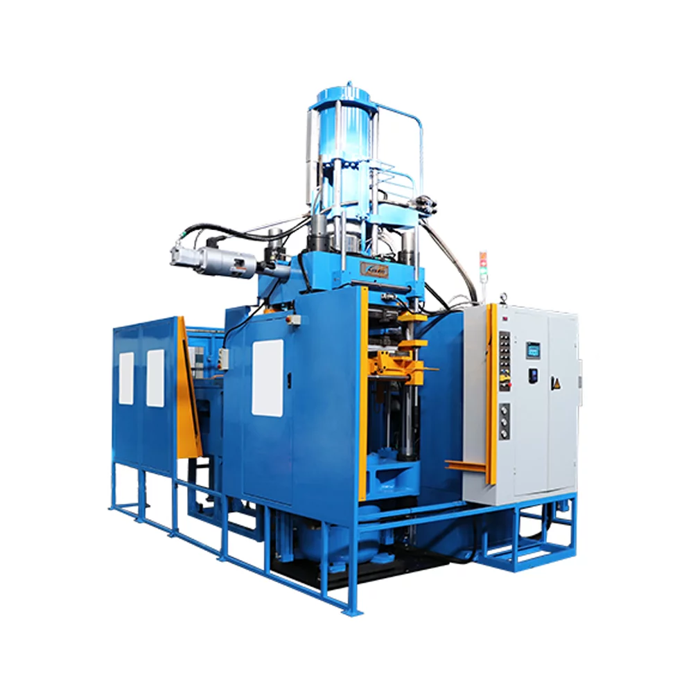
Production teams often see intermittent voids, surface pinholes, and weak seals when using a high-vacuum C-frame press. The immediate suspect is air entrapment during transfer or injection; the underlying culprits are usually venting geometry, shot flow instability, or inadequate vacuum performance. Early detection matters, and many engineers move quickly to retool without isolating root cause. For those using a c frame rubber injection molding machine, the machine’s vacuum venting path and transfer press interface must be validated before changing material or clamp settings.
Mechanics of porosity and air entrapment
Porosity arises when gas pockets remain trapped during the mold fill or during the cure cycle, then expand or migrate as pressure and temperature change. Key variables are shot flow speed, gate design, and vent placement. Vacuum removes free air but cannot fix poor gate dynamics; conversely, fast shot flow can shear gas into micro-bubbles that become stable pores. Clamping force and seal integrity also influence whether the mold experiences flash rather than trapped voids. Industry audits in Stuttgart and Nagoya have shown that small changes—0.5 mm in vent depth or modest gate taper—move defect rates dramatically.
Step-by-step troubleshooting checklist
Follow these practical checks in sequence, and log each change so results are measurable:- Verify vacuum system performance: leak rate, gauge accuracy, and vacuum hold time. Replace filters or service vacuum pumps if decay exceeds specification.- Inspect vent geometry: length, depth, and location relative to flow front. Short, shallow vents cause blowback; long vents may trap air.- Optimize shot flow and gate design: slow initial fill with a controlled transition reduces shear-induced micro-bubbles; adjust gate taper to promote laminar front.- Confirm clamping force and platen parallelism: uneven clamping causes local flash or suction pockets.- Review mold temperature profile and cure cycle timing: extended dwell can let dissolved gases outgas into voids during cooling.
Common mistakes and practical corrections
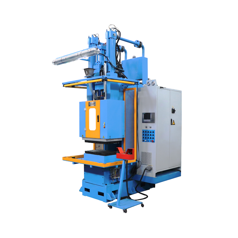
Teams often overreact by changing compound or increasing vacuum without addressing flow. This is ineffective—vacuum helps only when vents and transfer paths let air escape. Another common mistake: ignoring mold maintenance. Resin residue around vents and runner channels sabotages vacuum venting. Corrective actions that pay immediately include re-machining vents to spec, rebalancing runners for symmetric shot flow, and verifying the transfer press timing sequence. For operators considering equipment changes, compare a standard transfer press against a dedicated c frame rubber injection moulding machine for integrated vacuum control and synchronized clamping.
Alternatives and validation methods
Where defects persist, use non-destructive testing: ultrasonic inspection or micro-CT scanning will locate internal porosity without destroying parts. Trial runs with tracer gases or dyed fluid can reveal hidden flow stagnation. If changing molding strategy, pilot shorter cycles with instrumented mold sensors (pressure transducers at gate and cavity) to map shot flow and confirm vent performance. These diagnostics are faster than full material qualification and prevent wasted compound trials.
Advisory: three evaluation metrics to choose the right fix
Adopt these golden rules as selection criteria when deciding adjustments or new equipment:1) Defect reduction per change: quantify defect drop after a single intervention (vent rework, flow tune, vacuum pump service) rather than multiple concurrent changes.2) Process stability window: measure acceptable ranges for shot flow, vacuum level, and mold temperature that still produce zero-porosity parts.3) Mean time between failures (MTBF) of cured parts under application stress: prioritize solutions that improve MTBF rather than only reduce visible surface flaws.
Summary: focus first on venting and flow control, then on vacuum and machine synchronization; small, measured adjustments yield the largest returns. The work culminates in reliable cycles and predictable yields—precisely the engineering value HWAYI brings as a partner HWAYI. —